TI 2MTR-DYNO motor characteristics
- Details
- Published: Monday, 31 August 2020 19:51
Texas Instruments provides an evaluation kit for Permanent Magnet Motor control. The kit provides two three-phase motors, which are coupled together (motor+load), two inverters and a single microcontroller launchpad, to drive the two inverters. TI also provides software for Field Oriented Control (FOC) with Space Vector Modulation (SVM). Although the TI documentation for the inverter, the microcontroller and the included software. However, there is almost no information about the motors, so I had to search the internet, to see pictures on how to connect the motors to the boards for example, or read the TI code for the ratings of the motor.
The motor is the M-2310P-LN-04K Brushless Three-Phase permanent magnet motor. The datasheet of this motor can be found on the Teknic website. The motor has an internal encoder of 4000counts per revolution. It also has a 120degree commutator, which is less preferable for Field Oriented Sensored Control.
The motor comes with the Molex Mini-Fit connector. It is then output to two low-power connectors (encoder and commutator) and has the high power cables available as well.
Encoder connector (J6)
The encoder connector is a standard 5-way single row 2.54 spacing connector. The pinout is shown below:
1 - Blue: Encoder A pulse
2 - Orange: Encoder B pulse
3 - Brown: Encoder I pulse
4 - Red: 5V power supply (125mA at idle)
5 - Black: Ground
Pin 1 is considered as the the pin with the ^ symbol. The encoder count is 4000 per mechanical revolution.
Power connections
All the wires are AWG16.
Black: Phase A
Red: Phase B
White: Phase C
Motor Characteristics
The motor has a sinusoidal Back-EMF. The back-EMF factor is 4.64Vp/krpm (line to line) [based on the datasheet]
The motor has 4 pole-pairs [based on the datasheet]. The resolver offset needs to be learned by applying fixed vectors to the windings.
The Maximum Continuous torque is 0.2754Nm [based on the datasheet, converting from oz-in]
Based on the above, the torque constant 0383725Nm/Ap, whereas the maximum Iq current is 7A.
On the motor label, the rated speed is mentioned, which is 6000rpm (mechanical). The label also states that the rated continuous current is 7.1A.
Concerning electrical characteristics, I have done the following measurements to determine the inductance and resistance:
Phase resistance: Measured with a DMM (4-wire measurement) the phase to phase resistance, when the TI kit molex connector was connected. The average phase to phase resistance was 777mΩ (at 20degC), leading to an average phase to neutral resistance of 389mΩ. The value mentioned on the datasheet is 720mΩ (phase to phase), which perhaps doesn't considers the extra harness.
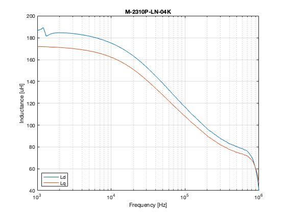
Concerning inductance, the datasheet states 400uH (phase too phase), which doesn't say much about the motor characteristics. NXP has a good application note, which explains how to align the rotor, to measure the Ld and Lq value, applying step voltage changes on the windings. I did follow the application note to align the rotors (applying fixed vectors), but then used a network analyzer to determine the inductance for different frequencies. The results of these measurements are shown in the figure below.