When needing to log or monitor data easily from embedded system, usually it's done offline, on a dedicated storage system, e.g. an SD card, SSD, USB stick etc. Data is also shown live via a serial terminal or on a screen. The debugger software can also be used, as some tools offer graphing capabilities as well. However, as the amount of parameters to be logged and monitor increases, monitoring all this data becomes more complicated. Example tools I've previously used have been
- STM-STUDIO-STM32 for the STM32 microcontrollers: I've used for converter prototypes during my PhD. This used the STLink debugger to get variable values and show them on the screen (without logging). This software is now obsolete and the STM32CubeMon is proposed
- Code Composer Studio for TI microcontrollers: Similarly used for converter prototypes. The Eclipse software from TI can plot cyclic buffers saved in the RAM of the microcontroller
- MATLAB GUI: Used for the initial telemetry data of the power converters of our developed Cubesat. The data would be sent via a wireless serial link (Bluetooth) and plotted in MATLAB in realtime
- COSMOS Telemetry: Used on my quadcopter project. This is I think the most complete open-source software for live telemetry. It can use data from Ethernet, serial or a database server. It has various graph and alerting functionalities.
- Grafana: Used for the solar microinverter system, installed in my university laboratory. A processor with a high level OS is needed to generate the SQL queries to insert the data on an SQL server. Ideal for low sampling frequency data (e.g. 5 second update rate). It can handle a large number of parameters (provided that the SQL server is powerful enough) and can plot on the fly different data.
All of the solutions above are for online monitoring of parameters. For saved data (with a sampling frequency in the range of kHz), it is first logged in an internal memory of the embedded system (e.g. SD card, RAM) and then offloaded to the host PC and plotted usually via MATLAB. The Zynq motor controller I've built is a prime example of this approach.
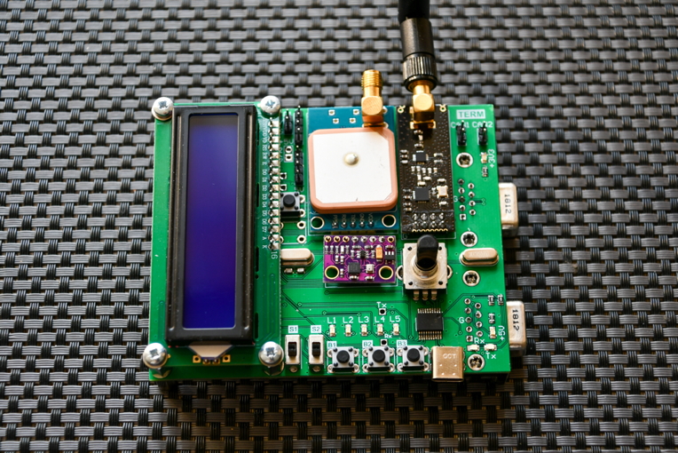
Even if there is a variety of solutions for monitoring parameters, none of them is very easy to implement especially if the number of parameters changes. Moreover, logging the parameter values in parallel to monitoring is also not straightforward. On the contrary, for automotive applications, where CAN is used, there is a large number of free and paid applications, which interpret CAN data, log and depict it. Modern embedded system cores (STM32, TI Delfino, Zynq) do support CAN via dedicated peripherals, so implementing a solution via CAN is easy. As I wanted to use this platform for my existing systems (particularly the quadcopter, the Zynq motor controller and another system I have in preparation), I decided to build a dedicated board that would have multiple functions:
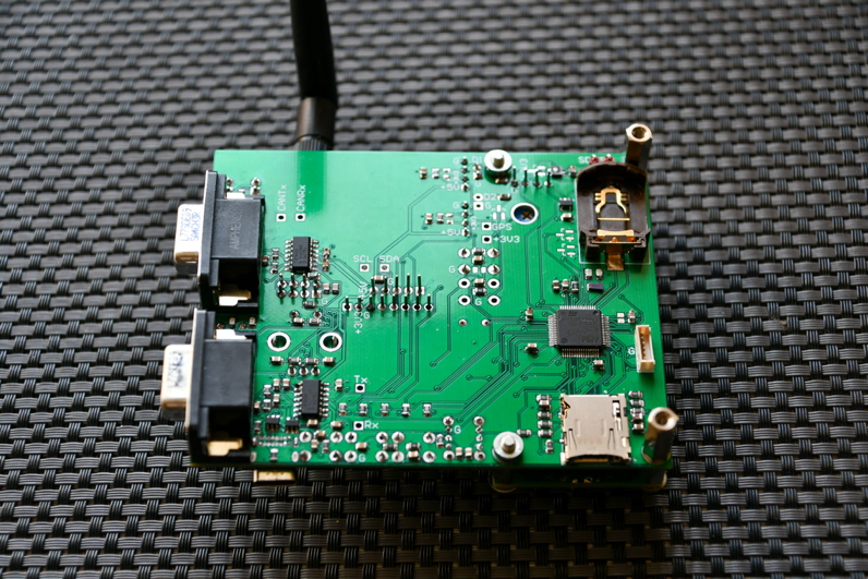
- Ability to interface with two CAN channels and USB for logging and control via the host PC software
- Communication via the existing embedded system via a wired (UART) or wireless (nRF24L01) channel
- GPS, accelerometer and environmental sensors
- Analog/Digital inputs for extra sensors logging
- USB-C port for battery use with a battery bank
- SDCard for logging of the gathered data if a host PC is not available
- Real time clock with battery, to have the correct time on the logged data, even if the GPS signal is weak
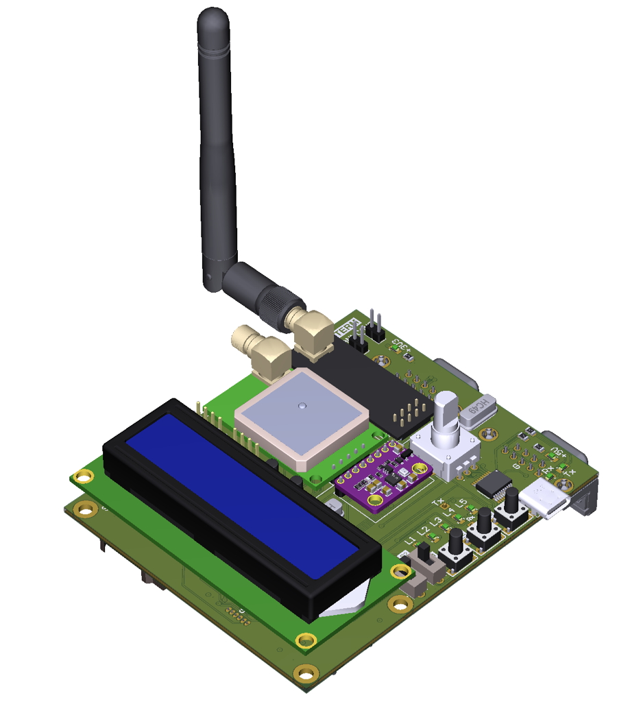
- LEDs, buttons, rotary encoder and 16x2 dot matrix display, for the Human Machine Interface
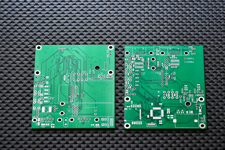
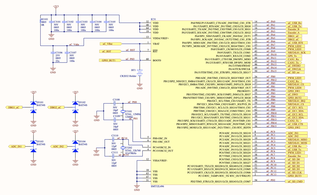
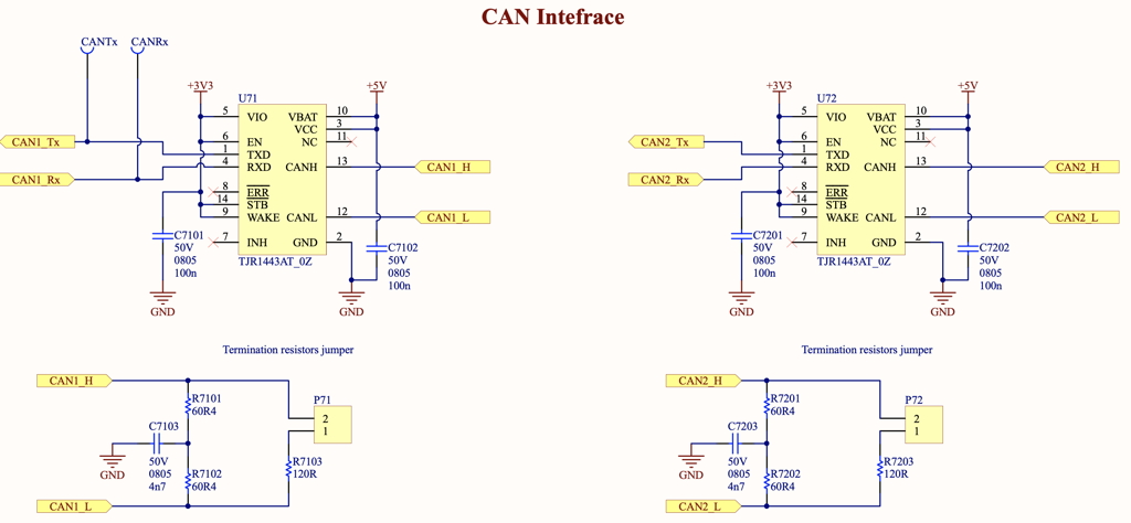
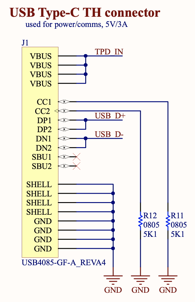
I based the board on an STM32L4 microcontroller which I had from the previous quadcopter project. It has an LQFP-64 so plenty of I/O to connect to the different peripherals. The schematics of the microcontroller board can be seen below. I've used all available pins of the microcontroller so that the board can be used not only as a wired/wireless link to CAN, but also as a standalone sensor array and logger. Concerning the CAN transceivers, I selected the TJR1443 ICs, which are readily available and also support CAN-FD for future projects. I didn't use any of their low power or diagnostics, as this would use more pins from the microcontroller. But all these features are nice to haves for a low power design, particularly if used in combination with an L4 (low power) family microcontroller. Moreover, this is the first project I've implemented with USB-C, the connection diagram of which is also shown below. I opted for a through-hole connector, to provide better ruggedness while plugging/unplugging. Compared to the typical USB mini-B or micro-B, two extra 5.1kΩ resistors are needed. However, this provides 5V at 3A, compared to 100mA that the standard USB protocol allows.
The circuit was implemented on a four-layer PCB, though given its limited complexity (100 different components on the board), a two-layer PCB would have sufficed. The internal layers were used for power distribution, whereas the externals were used for the signal traces.