As part a collaboration with my former laboratory in the university, I assisted in designing a solar microinverter, to connect a 200W solar panel to the low voltage grid. Compared to typical university made converters, this system needed to be robust and autonomous, as it would be assembled once and remain next to the roof solar panel afterwards. Therefore, multiple extra considerations, both hardware, software as well as mechanical needed to be included, for the reliable operation of the system.
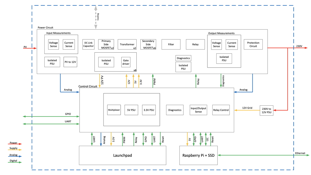
The power electronics is based on an interleaved flyback converter, the fundamental operation of which was part of my PhD thesis. The flyback converter offers galvanic isolation and high voltage step-up ratio through the transformer, whereas it also allows for an easy, sensorless control if operated in Discontinuous Conduction Mode (DCM). The interleaved design offers the extra advantage of needing a smaller transformer (lower height), which is important for a microinverter, where the height of the unit is the one that matters. Moreover, it increases its efficiency and divides the temperature rise due to losses. The converter needs a large input DC link capacitor bank, implemented using electrolytic capacitors, to decouple the sinusoidal power oscillation of the single-phase output. Those capacitors need to be kept cool, to increase the converter lifetime. A high frequency L-C-L filter is used to reduce the switch ripple of the current supplied to the grid. Apart from the main components, analyzed above, there are more components required for the converter operation. Power supply bricks are used to provide the isolated power for the gate driving and sensor circuits. Another supply gates power from the solar panel, as a backup power to keep the control circuit working in case of a grid cut. A relay is also connected on the grid side, to galvaincally isolate the converter from the grid, when not in operation.
On the control board side, there are the diagnostics circuits, the power multiplexer that determines the power source for the circuit and all the analog measurements frontend. The main purpose of the control board is to house the connections to the TI microcontroller and the Raspberry Pi. The TI microntroller performs all the low level control (PWM strategy of the primary and secondary side switches, relay operation, Maximum Power Point Tracking, de-rating) and sensing (input voltage and current, output voltage and current, auxiliary power supplies and temperatures). This data is then transferred to the Raspberry Pi, which logs it internally on its database and publishes it via a dedicated webpage.
The microinverter frontpage can be found in the following link.