Teardown and operation of an MGE NOVA AVR 600
- Details
- Published: Saturday, 03 October 2015 10:44
The MGE Nova AVR 600 is a ten year old model used to power a single computer (360W/600VA). In 2007 MGE was purchased by Schneider and merged with APC UPS series. Since I had both an MGE and an APC UPS before they merged, I have the opportunity to show the differences and similarities on their design and their operation.
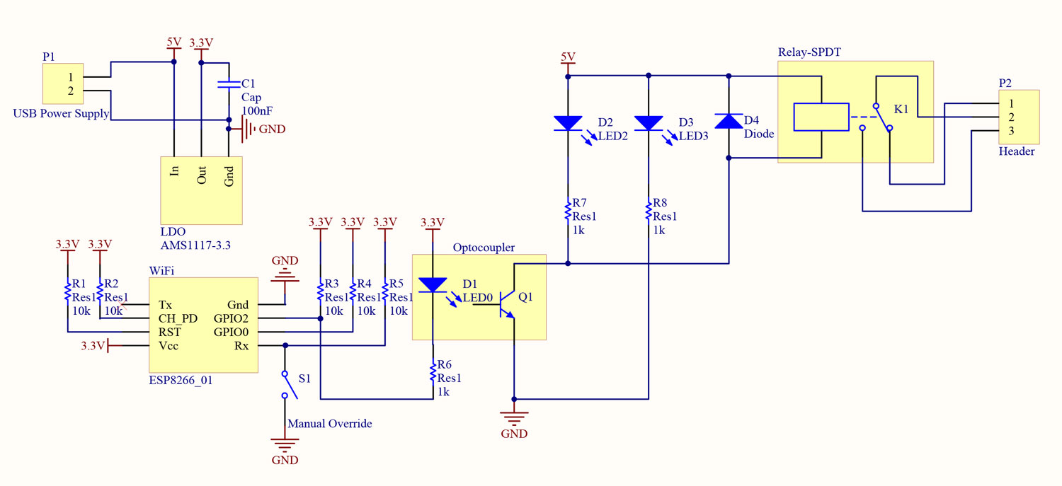
To begin with the MGE Nova UPS, the schematic of the power stage is shown in the following figure.
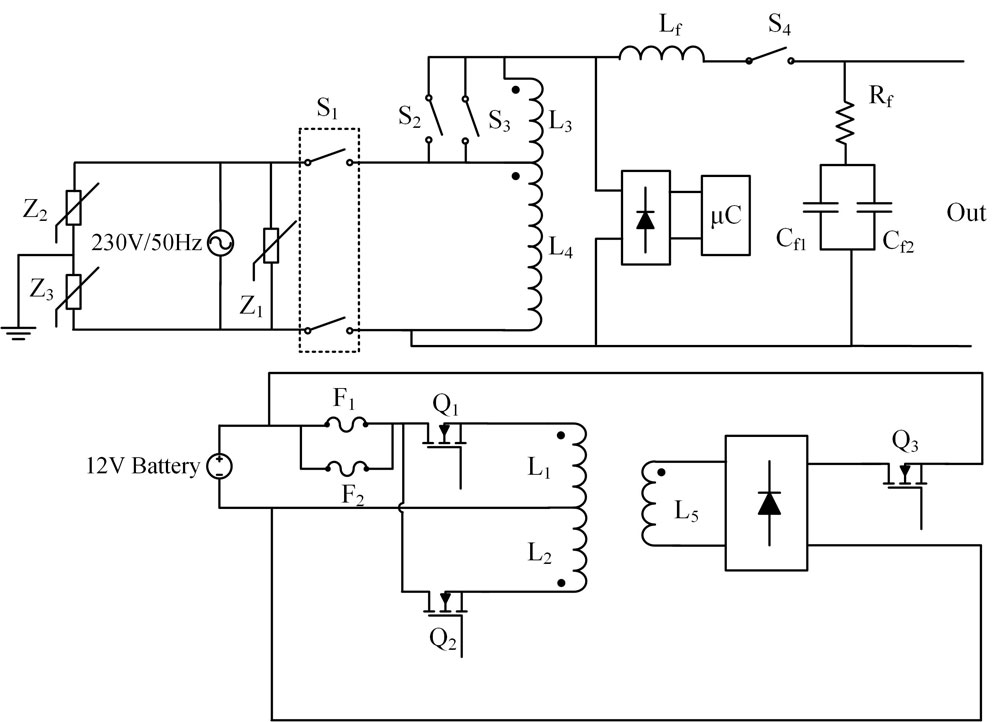
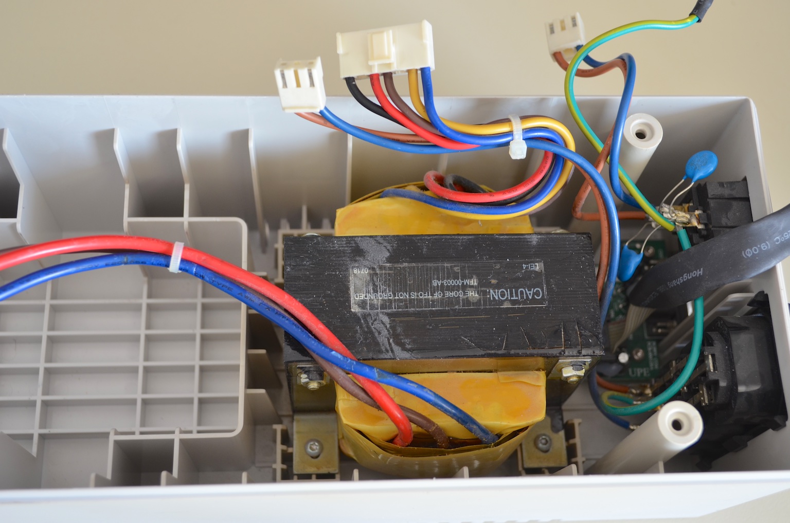
The ac grid is connected to the left and the output plug to the computer is on the right. The battery connection is on the bottom and together with its inverter and rectifier charger. The main component of this UPS, as well as on the majority of the UPSs of this power range is the low frequency (50-60Hz) transformer with multiple windings.
The inductance as well as the ohmic resistance for each winding are:
- L1: 1mH, 100mΩ
- L2: 1mH, 100mΩ
- L3: 700mH, 8.8Ω
- L4: 25mH, 8.5Ω
- L5: 6.3mH, 300mΩ.
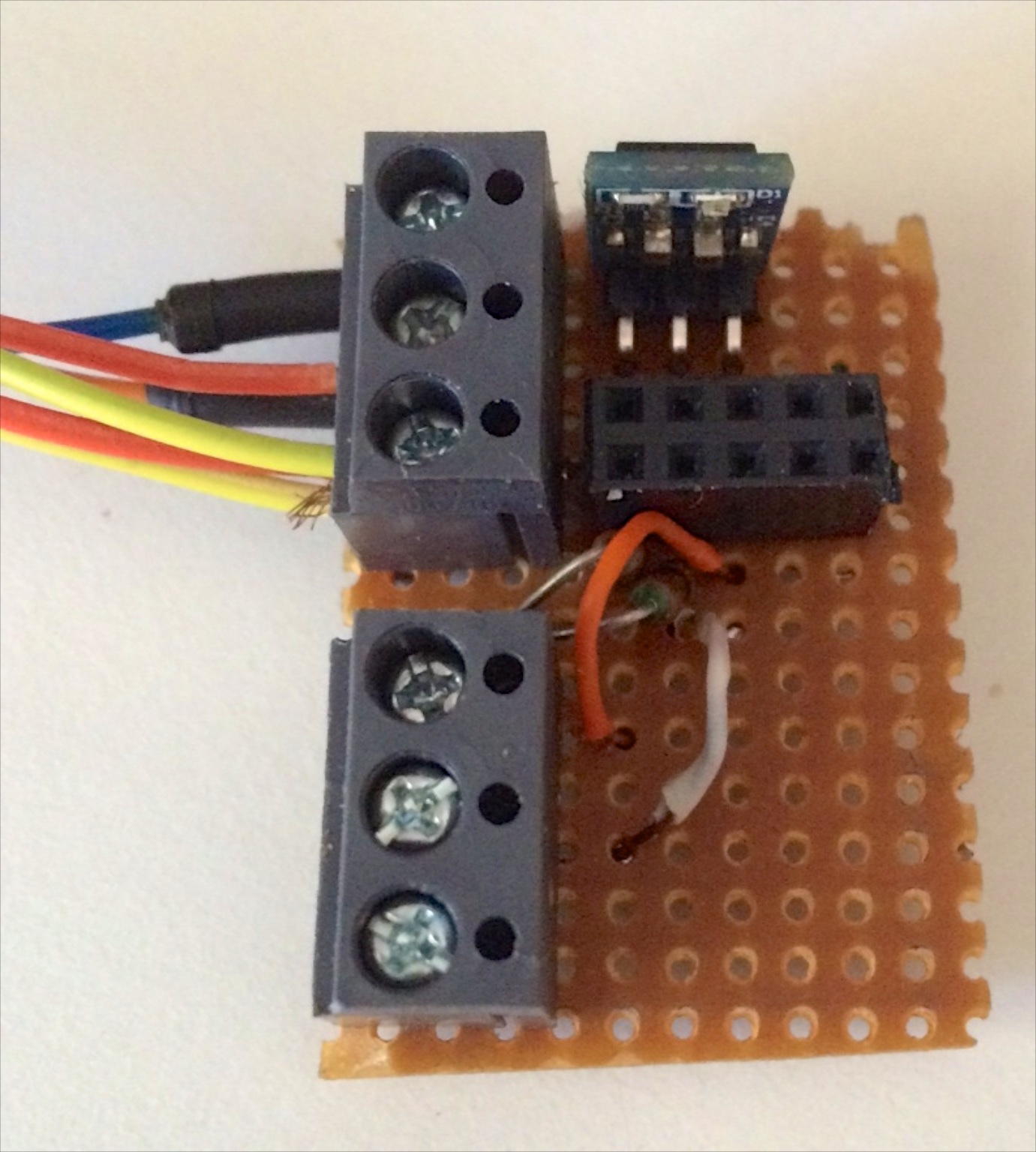
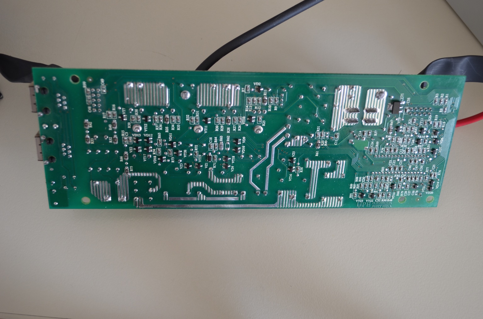
The main power board is shown in the next image. The ethernet connectors on the left are surge protected via MOVs (TVR 07471 - 470V). On the top, the relays S1-S4 switch the power depending on the grid voltage value. The heat sink on the bottom houses four transistors (for the inverter) and one regulator. The microntroller is housed on the right hand side of the board 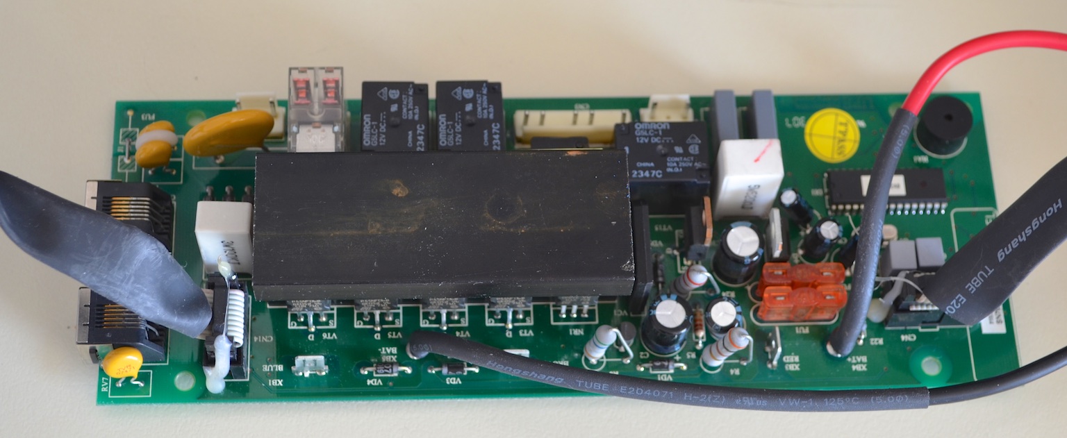
Two fuses in series with the 12V battery are connected in parallel (40A each). 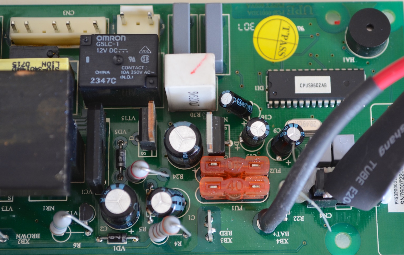
The switches S1-S4 are shown in detail, together with the low pass filter Lf, Cf, Rf. Cf consists of two 100nF capacitors connected in parallel. 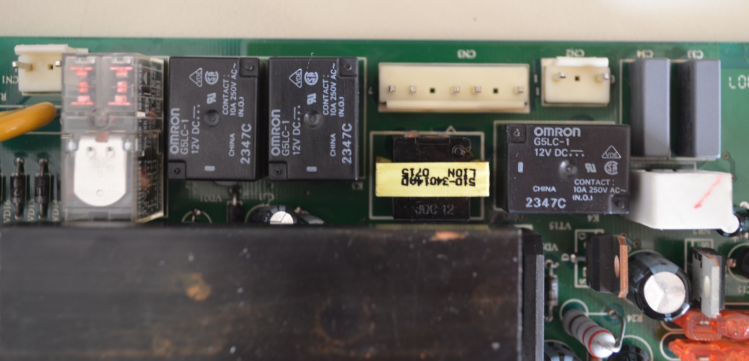
The inverter transistors are the ST P55NF06 (60V, 50A, 16mΩ). Their connected in parallel in pairs. The LM217 on the right is a linear regulator for the auxiliary circuit. 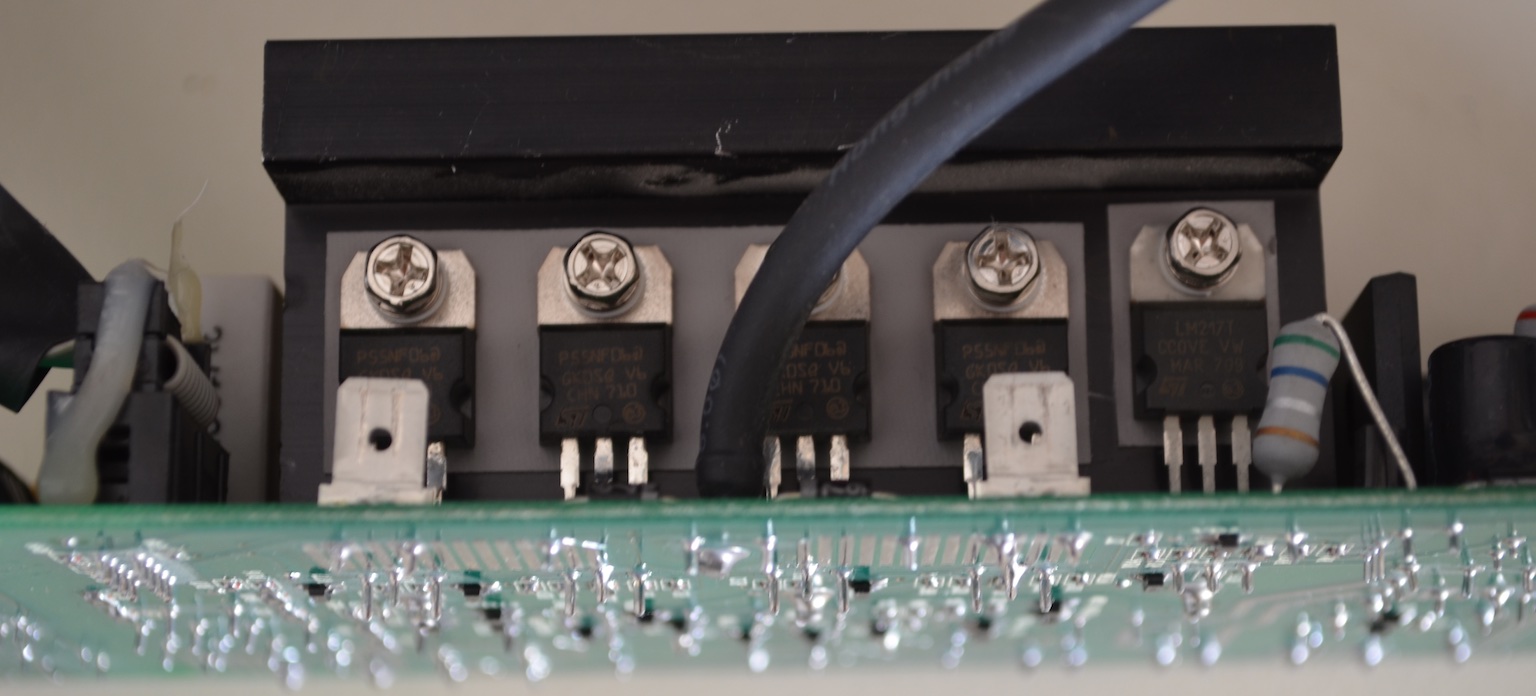
Whereas on the top all the components are through hole, on the bottom their are many SMD components. The high current traces are soldered in order to have lower resistance. 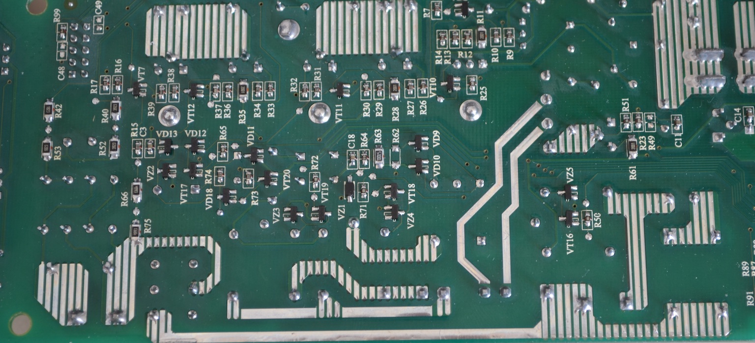
Finally, the MOVs for the surge protection of the main power are not found on the board but are soldered directly on the plugs (not the neatest solution). The MOV type is the TVR 20471 (470V). 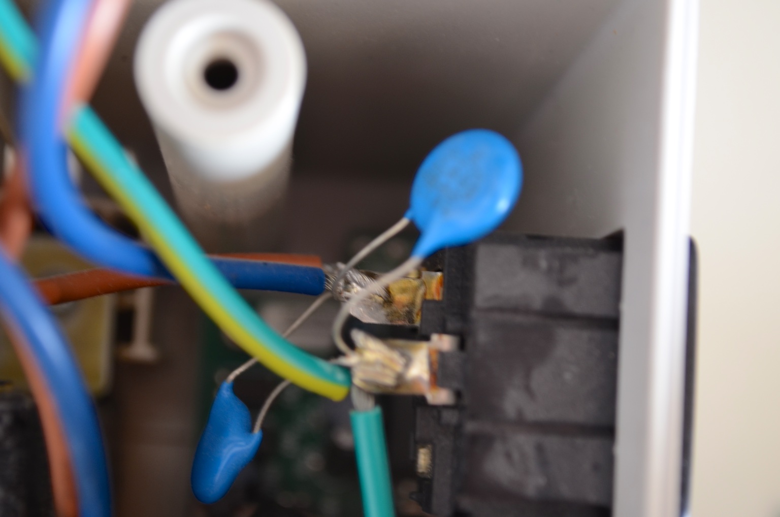
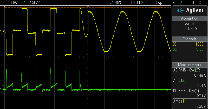
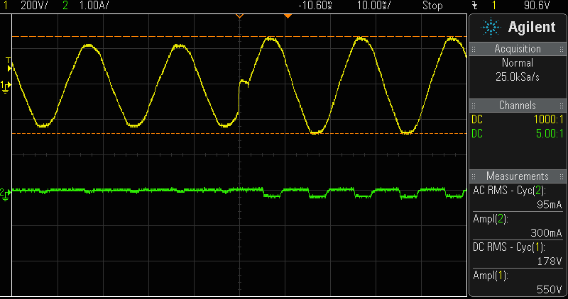
The operations that a UPS must do (and will be shown though oscilloscope graphs below) are: normal operation, operation under undervoltage, operation from battery, charging of battery, surge protection. To begin with, the simplest operation is the surge protection, achieved by Z1, Z2 and Z3. Under normal operation, the input be directly connected to the output. This is achieved by having all switches (S1-S4) on. When there is an undervoltage, the UPS does not supply the voltage via the battery. The battery is only employed when the grid is lost. So, this can be done by using an autotransformer formed by L3 and L4. If S2,S3 switch off, then the voltage is stepped up. T0 start with the oscilloscope waveforms, I first tested the UPS operation when an undervoltage occurs. The UPS as shown in the schematic (and as validated by the measurements as well) has a single auxiliary tap to support operation when in undervoltage. So, by using an external autotransformer I began with a voltage input of 230V and slowly decreased it. At 167V S2 and S3 switched off, activating the auxiliary winding L3. So the voltage was stepped up from 167V to 193V which continuous to seem rather low. This operation is shown in the following figure. Notice that the battery charging current (shown in green) is a higher when the auxiliary tap is activated. The opposite action is observed when the input voltage rises. The tap is deactivated when the input voltage reaches 175V, so there is a hysteresis control.
Now in the previous waveform the battery charging current waveform was shown. To elaborate a bit more, the following figure shows the charging current (negative) in detail. The battery is charged with a pulse switching current when the instantaneous grid voltage (and consequently the corresponding voltage of L5) reaches a specific threshold.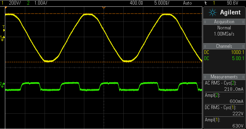
To continue with the undervoltage operation, the UPS switches to battery mode when the grid voltage drops bellow 145V, an extremely low value. This transition is shown in the following figure. Before the transition the battery is being charged (negative current). After the transition, the battery supplies the current so the current is positive. 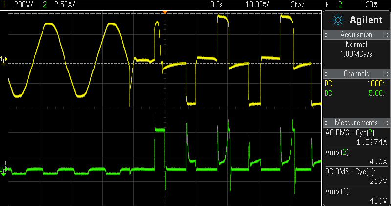
The output voltage of the UPS is far from a sinusoidal wave. However, the principal loads of UPSs are computer power supplies and so a sinusoidal voltage is not a strict requirement. When the transformer of the UPS is loaded, the waveform starts to seem like a sine wave. The battery current is constant.
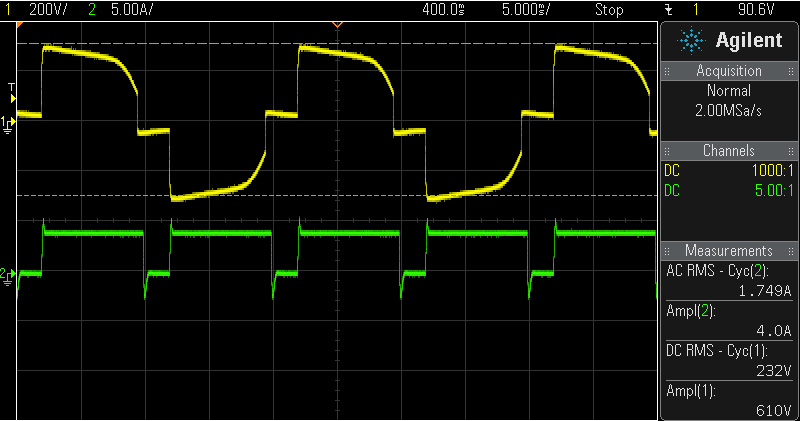
During startup in battery mode, there is a peak of the buttery current up to 10A for the first cycle, possible to charge the circuit capacitors. The peak is then decreased to about 5A. 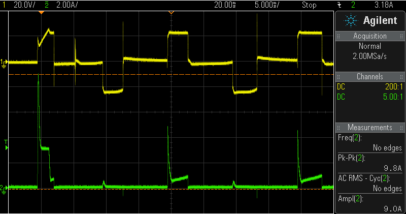
The inverter transistor Drain-Source voltage is zero when it is ON, 12V when no transistor is conducting and ~24V when the other transistor is conducting. 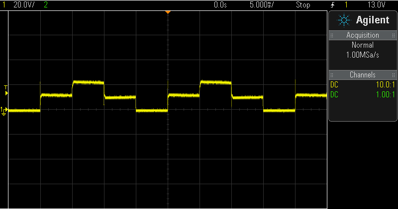
Finally, when the grid is again present, the UPS switches from battery supply to grid supply. The threshold to consider that the grid is present is 150V.