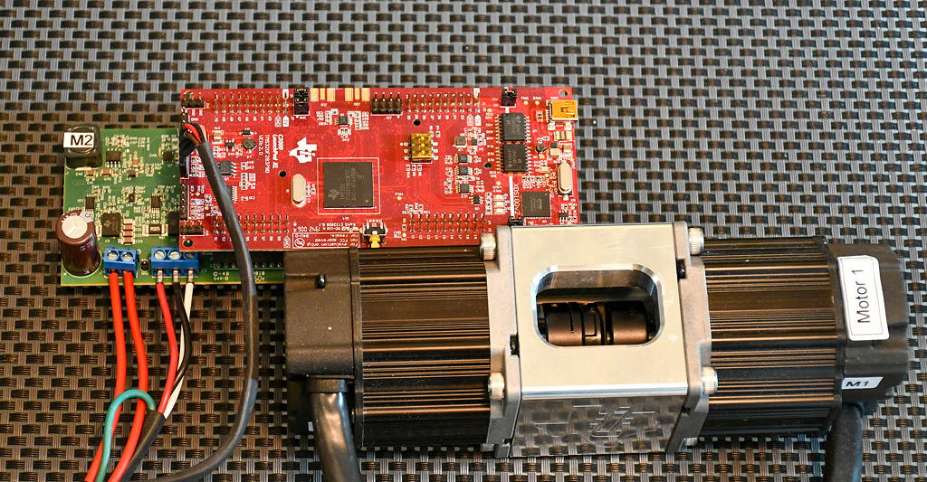
The TI 2MTR-DYNO is a back-to-back permanent magnet synchronous motor system, with the two motors coupled together. The motors are driven by two inverters (Ti offers evaluation boards) and is controlled by a Delfino microcontroller. I have used TI's TMS320F28379D Launchpad to drive one of the two motors, while I was developing the hardware and software for the main motor. The load motor (controlled by the TI software) is in speed control mode, so it keeps a constant speed (positive, negative or zero), which is set by the Code Composer Studio code variables. The TI application note SPRACB8A explains how to get the code, connect the inverter and run the system in various different modes. I will focus in how to setup the system to have a single motor, operating in speed control mode, in order to act as a load during motor control development for the coupled motor.
The characteristics of the 2MTR-DYNO motors are detailed in a previous post. I am using the BOOSTXL-3PhGaNInv module, which consists of a three-phase GaN inverter, together with phase current sensors and a small level of protection circuits. I am have connected the inverter to the lower side BOOSTXL connectors of the Delfino board (J5-J8), as it was easier in terms of assembly. This means that the encoder of the motor, needs to be connected to the QEPB connector (with the triangle on pin1 of the connector). On the BOOSTXL inverter board, the DC supply and the motor phases need to be connected.
On the application code, following the Application Note, I set the 'MOTOR2_DRV' to 'GaN_BP', which is the default and set the 'BUILDLEVEL' to 'FCL_LEVEL5', which is the one for speed control. I have tested all previous build levels beforehand, to ensure the correct operation of the setup and see the voltage/current waveforms of the system and would recommend building on the previous levels as well. However, this post is about using a single motor as a load for the testbech. As soon as I set these parameters in the configuration file (FCL_SFRA_XL_DualServo-Settings.h), I built the project.
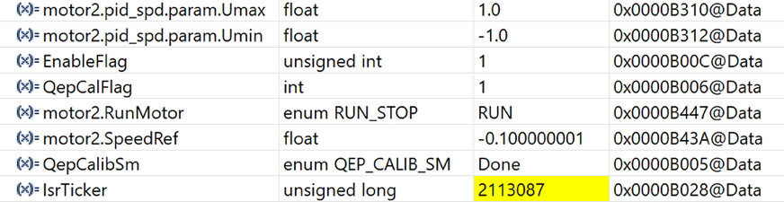
I then started the CCS debugger and loaded the key expressions, as shown below. To run the motor as a load for the testbench, the steps are the following:
- Hit 'Resume' on the debugger, to start the application code on the processor core
- Enable 'Continuous Refresh' on the expressions, to have a live update on the values
- Switch on the DC power I usually set it to 30V. The GaN inverter is compatible with up to 48V
- Set 'EnableFlag' to '1'. Monitor the 'IsrTicker' that it's constantly updated
- Set 'QepCalFlag' to '1'. Set 'QepCalibSm' to 'Qep2'. This will rotate the motor to find the encoder index
- Wait for the encoder index learn. The 'QepCalibSm' will change to 'Done' after that
- Set 'Motor2.RunMotor' to 'RUN'. The inverter will start switching
- Set 'motor2.pid_spd.param.Umax' to '1.0' and 'motor2.pid_spd.param.Umin' to '-1.0'. This will give maximum capability to the inverter, in order to have the speed follow the reference value, under any torque on the axle.
- Set the reference speed by setting the parameter 'motor2.SpeedRef'. The value can be either positive or negative, and it is a ratio of the maximum speed.